
TM 11-6660-218-12
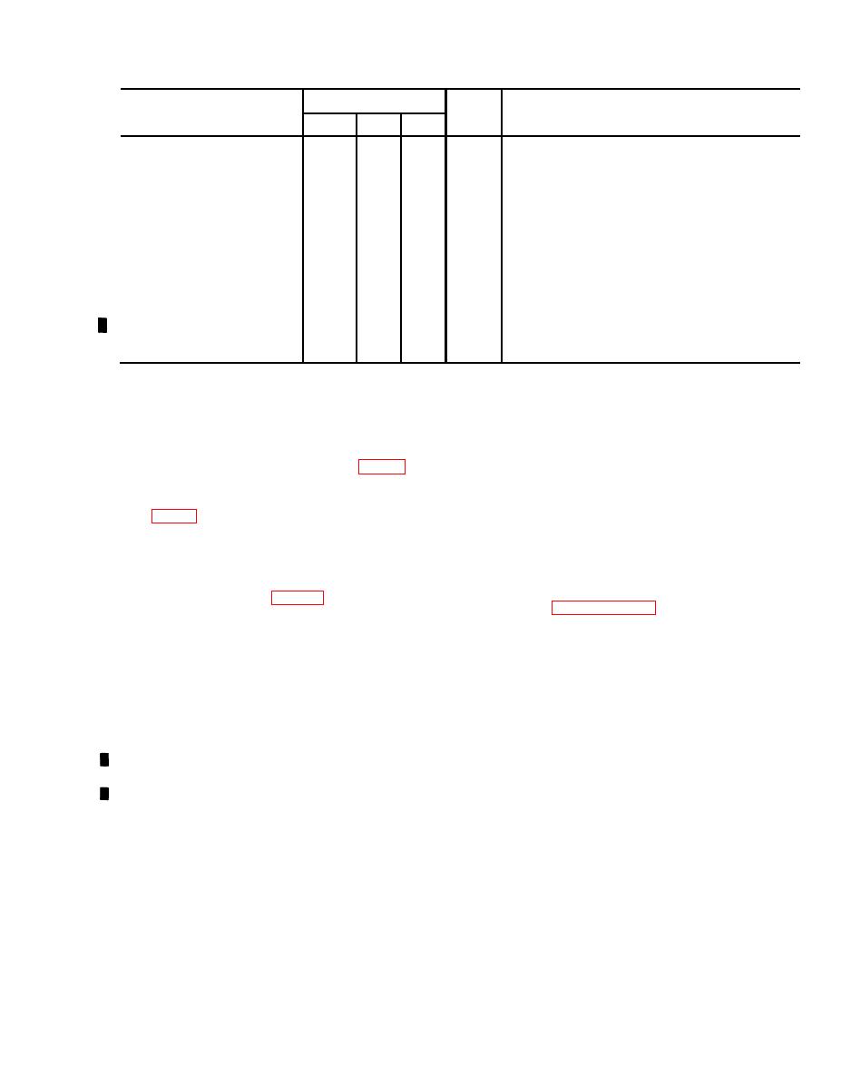
Dimensions (in.)
Volume
Contents of box
Box No.
Height Width Depth
(cu ft)
Nozzle ML-196
Straightedge, ML-357/ GM
Thermometer, general
Psychrometer ML-224
Slide Rule ML-59
Clock and watch oil
Lubricating oil
Pipe nipple
34
11.2
14 and 15 of 124 __ _ _ _ _ _ _ _ _ _ _ _ _
24
24
Balloon ML-635/UM
48
16 of 124 _____ _ _ _ _ _ _ _ _ _ _
9
66
24.1
Balloon Inflation and Launching Device
I
ML-594/U
27 1/2
6.2
211/2
181/2
17 of 124 ______ _ _ _ _ _ _ _ _ _ _ _ _ _
Calcium Hydride Charge ML-304A/TM
8
23
1.8
18 thru 97 of 124_ _ _ _ _ _ _ _ _ _ _ _ _
17
Calcium Hydride Charge ML-305A/TM
28
18
8.6
22
Calcium Hydride Charge ML-587
29
9.6
22
26
98 thru 106 of 124 --_ _ _ _ _ _ _ _ __ _ _ _
Radiosonde Set AN/AMT-4(*)
2.4
15
13%
21
Battery Pack BA-259/AM
107 thru 124 of 124
a. Tool Equipment TE-33.
2-3. Siting
The met. station should be centrally located with
b. Wrench TL-112.
respect to the organization it services. It should
c. Hammer HM-3.
beat or near the mean altitude of the using unit
and, if possible, not over 600 feet above the mean
2-5. Installation Instructions
altitude. The balloon launching site (fig. 1-1) must
After the balloon launching and plotting station
be in a clear area, preferably with no obstructions
sites have been selected, install the equipment as
above 30 elevation when the rawin set is being
follows :
used (fig. 12 ), and 6 elevation when the theodo-
lite is being used. A source of water should be
a. Installation of Equipment at Balloon Launch-
available for the operation of the hydrogen genera-
ing Site.
tor set and the area should have good drainage
(1) When electronic observations are to be
for the disposal of water and waste chemicals. The
made, position the rawin set as described
plotting station site (fig. 11 and 1-2) can be
in paragraph 2-3 and place the Power
located at a distance from the balloon launching
Unit PU-620 so that the noise of the
site, depending on situations that prevail. If visual
generator will not interfere with the
balloon observations are to be made, the plotting
work personnel. The length of the power
station can be out of sight of the balloon launching
cord (46 meters) limits the distance.
site, because the operator of the theodolite will
(2) Place Radiosonde Baseline Check Set
transmit all information back to the plotting sta-
AN/GMM-1 so it is shielded from the
tion through the head and chest set. If electronic
direct or reflected rays of the sun. Make
observations are to be made with the rawin set,
sure that no obstacles or metallic ob-
it will be necessary to locate the rawin set no
jects block the transmitted signal be-
farther than 30meters from the balloon launch-
tween the baseline check set and the
ing site, and the plotting station site no farther
rawin set main assembly.
than 62 meters from the rawin set. If possible,
(3) Select an area of operation so that the
select the plotting station site so that it affords
location and altitude of the station can
some cover.
be established on a large scale map. Es-
2-4. Tools Required
tablish a line of direction to true North;
use the compass on the theodolite and the
The following tools are required for the installa-
area declination or by a survey.
tion of the met. station:
2-3
Change 8


 Previous Page
