
TM 11-6660-200-14
5-27.
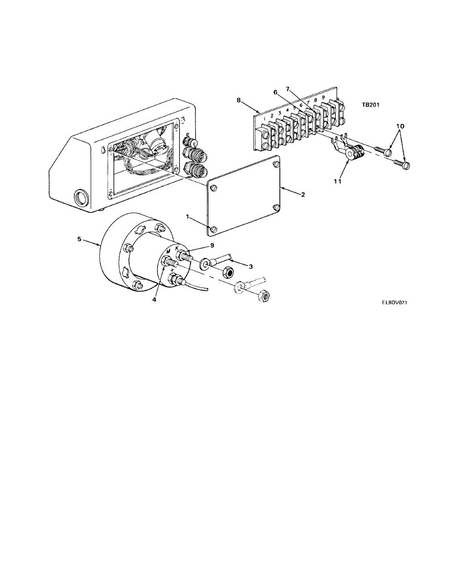
WINDSPEED INDICATOR RESISTANCE TEST.
TOOLS:
Digital multimeter, Fluke 8600A
1.
Loosen four turn-lock fasteners (1) and remove rear cover (2).
2.
Connect orange wire 4-14 (3) to terminal M(4) on windspeed indicator (5).
3.
Using digital multimeter, check for 1,150 ohms 6 ohms resistance between terminals 6 (6) and 7 (7) on terminal
board TB201 (8).
4.
Remove and reconnect orange wire 4-14 (3) to terminal K (9) on windspeed indicator (5).
5.
Using digital multimeter, check for 1,150 ohms 6 ohms resistance between terminals 6 (6) and 7 (7) on terminal
board TB201 (8).
6.
Loosen two screws (10) and resistor R201 (11). Retighten two screws (10).
7.
With orange wire 4-14 (3) on terminal K (9), and using digital multimeter, check for 2,300 ohms 11.5 ohms
resistance between terminals 6 (6) and 7 (7) on terminal board TB201 (8).
8.
Remove and reconnect orange wire 4-14 (3) to terminal M (4) on windspeed indicator (5).
9.
Using digital multimeter, check for 2,300 ohms, 11.5 ohms resistance between terminals 6 (6) and 7 (7) on
terminal board TB201 (8).
10.
Loosen two screws (10) and install resistor R201 (11). Tighten two screws (10).
11.
Install rear cover (2) and tighten four turn-lock fasteners (1).
NOTE
If readings are insufficient or excessive, refer to higher category of maintenance.
5-36

 Previous Page
