TM 11-6660-218-12
e . Upper Air Wind Direction and Windspeed
(5) Set the index mark on the anemom-
eter range selector knob at the ap-
(Visual Observation). Three observers are
required for this operation; one observer
propriate
(estimated)
windspeed
range (0 to 8 or 0 to 40).
releases the balloon, the second observer oper-
ates the theodolite set (after the pilot bal-
(6) Without moving the anemometer
loon is released, this operator will assist the
from the position in which it was
theodolite set observer), and the third observer
held to determine wind direction
is located at the plotting section and indicates
((2) above), read the windspeed
when the theodolite set readings should be
from the velometer scale. Be sure to
taken. He also records the readings on DA
view the velometer pointer directly
Form 4469.
from the front to avoid an erroneous
(1) The plotting section gives the order'
reading. If the pointer fluctuates con-
to release the pilot balloon. When pos-
siderably, read the high and low
sible, the pilot balloon should be re-
points and average the two readings.
leased approximately 100 meters
Note the windspeed in whole knots
downwind from the theodolite; this
(MP433A/PM), or miles per hour
will reduce the tracking error and in-
(ML-497/PM)
(mph)
(rounded
crease the accuracy of low-level winds.
to the nearest whole number).
(2) When the order is given to launch
(7) Correct the observed windspeed-
the pilot balloon, the plotting section
reading for the effects of varying air
presses the start pushbutton of the
density; use the windspeed correc-
timer (fig. 120).
tion factor chart furnished with the
(3) The theodolite observer tracks the
anemometer. Instructions for using
pilot balloon with the open sights
the chart are printed on the chart.
and the tracking controls disengaged.
(8) Record the correct windspeed to the
The first elevation and azimuth an-
nearest whole knot, or mph.
gles are read to the nearest whole
degree; then the operator changes to
the telescopic sights, aligns the
sights on the pilot balloon, and en-
gages the tracking controls. The pilot
balloon is tracked, using the track-
ing controls for the remainder of the
flight.
(4) When the time recorder commands
WARNING, the observer adjusts the
tracking controls with the crosshairs
centered on the pilot balloon. At the
command READ, he ceases tracking
and reports to the plotting section
the elevation and azimuth angle of
the balloon to the nearest 0.10.
(5) The theodolite set operator at the
plotting section enters the readings
on DA Form 4469.
(6) Five seconds before each reading, the I
plotting section will warn the the-
odolite set operator to make an exact
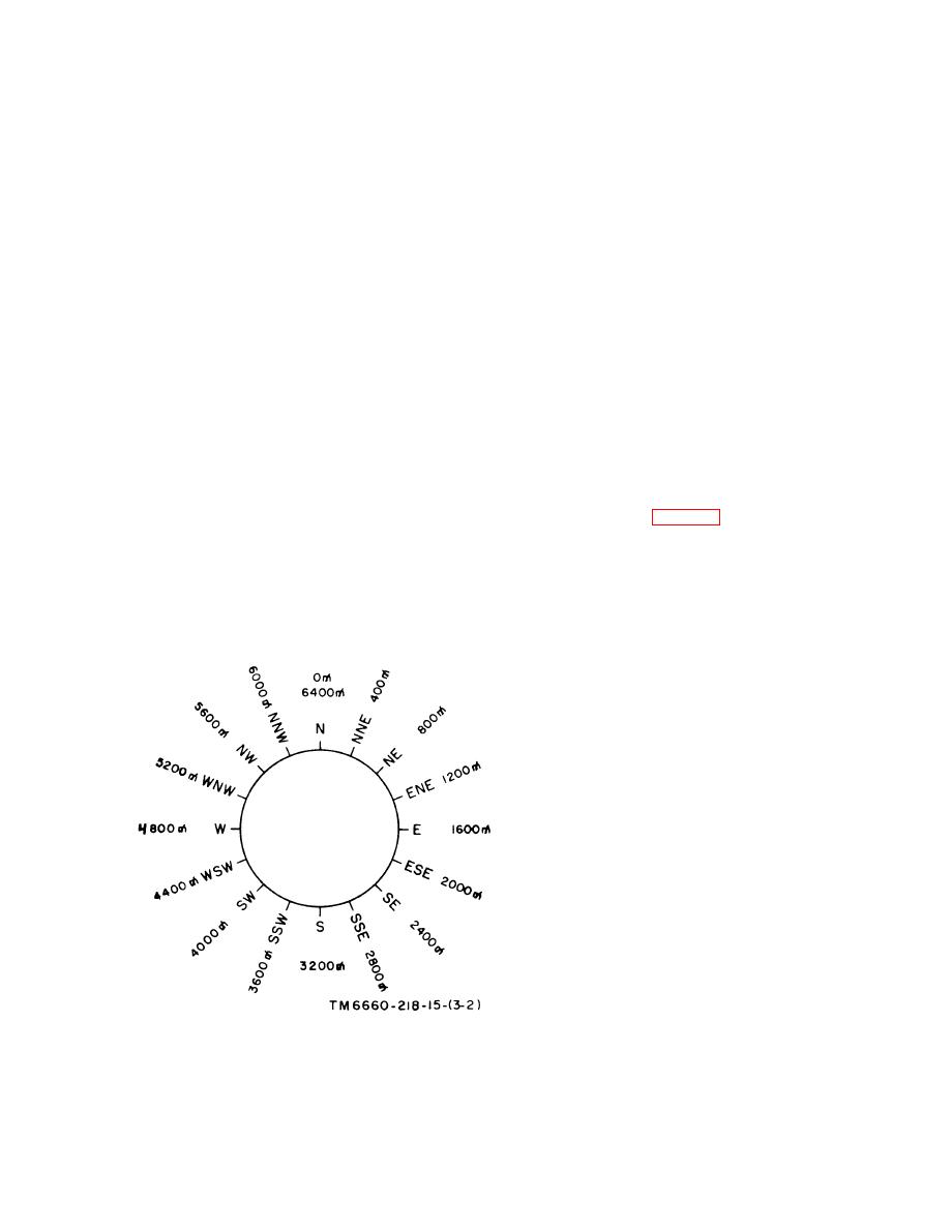
Figure 32. Mils scale conversion.
AGO 0Q29A
Change 8
3-9


 Previous Page
