
TM 11-6660-200-14
4-28.
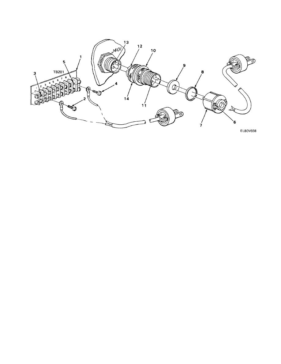
POWER CABLE REPLACEMENT. (CONT)
DIRECT WIRING TO TB201
REMOVAL
1.
Loosen four turn-lock fasteners on rear of indicator and remove rear cover.
2.
On TB201 (1), remove screw (2) from terminal 1 (3) and screw (4) from terminal 9 (5) and remove cable
from indicator.
INSTALLATION
1.
Install cable into indicator.
2.
Connect one wire to terminal 1 (3) with screw (2) and other wire to terminal 9 (5) with screw (4).
3.
Install rear cover of indicator and tighten four turn-lock fasteners.
CONNECTION TO J401
REMOVAL
1.
Unscrew plug P401 and pull free from jack J401.
2.
Loosen two screws (6) and unscrew wire retainer (7).
3.
Pull wire retainer (7), washer (8), and rubber bushing (9) up wire and away from connector body (10).
NOTE
For correct soldering methods, refer to TB SIG 222.
4.
Unsolder two wires from connector body pins (11).
5.
Remove rubber bushing (9), washer (8), and wire retainer (7) from cable.
4-40

 Previous Page
