TM 11-6660-200-14
4-16. INDICATOR CABLING INSTALLATION.
PRELIMINARY PROCEDURE: Assemble indicator (para 4-9).
NOTE
Steps given are typical for both flexible and conduit interconnection cables.
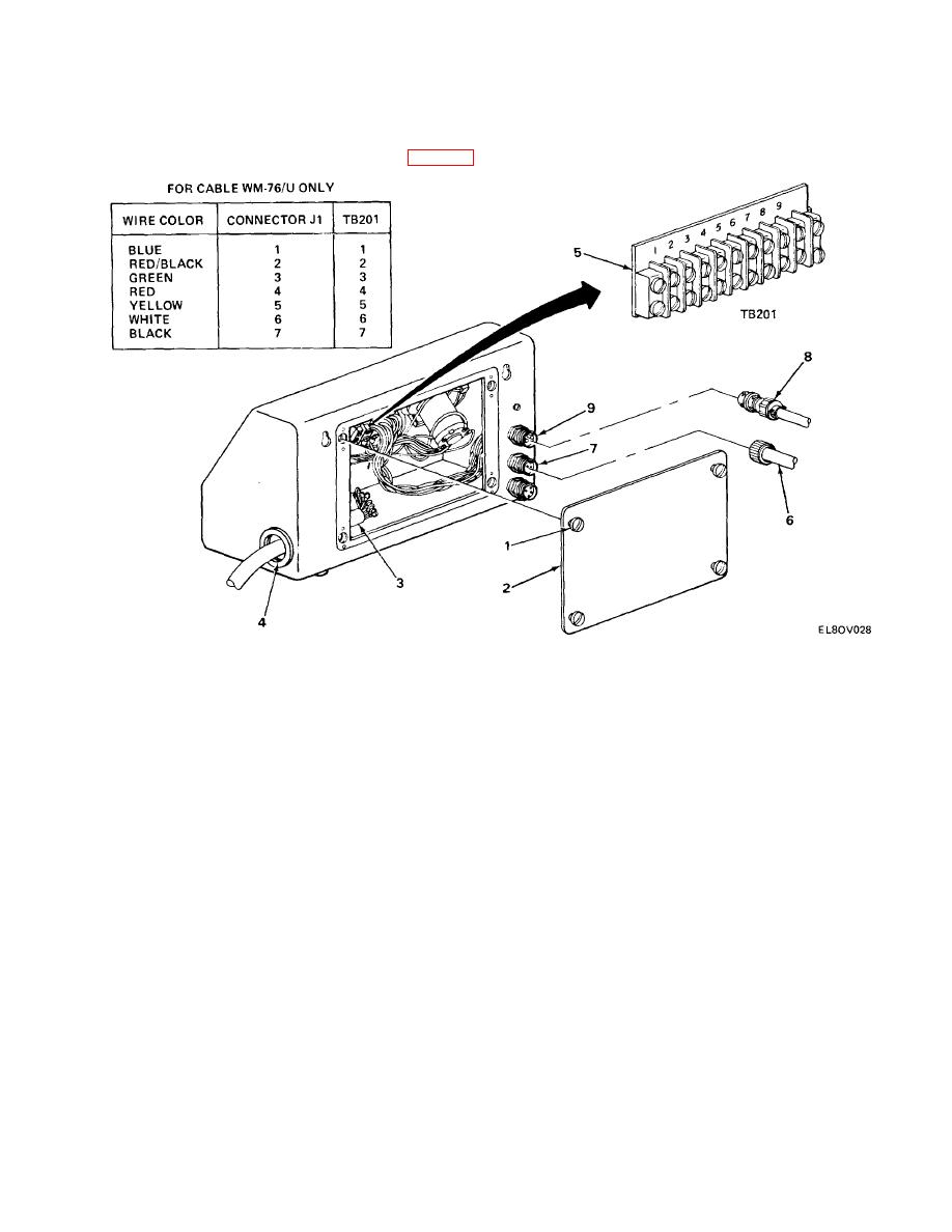
When using cable WM-76/U, use color-code diagram shown.
When using substitute cable, use color-code diagram generated when wiring connector
J1 to transmitter.
For indicators with internal wiring, perform steps 1 through 4.
For indicators with external plugs, perform steps 5 and 6.
1. Loosen four turn-lock fasteners (1) and remove rear cover (2).
2. Install prepared cable (3) through hole (4) on side of indicator.
3. Connect wires as shown in diagram for cable WM-76/U or diagram generated for substitute
cable to TB201 (5).
4. Install rear cover (2) and tighten four turn-lock fasteners (1). Perform step 6.
5. Connect interconnection cable plug P402 (6) to receptacle J402 (7).
4-22


 Previous Page
