
TM 11-6660-200-14
5-14. INDICATOR CONNECTOR PLUG REPLACEMENT.
MATERIALS/PARTS:
P401-connector, plug, electrical, NSN 5935-00-552-2369
P402 and P403-connector, plug, electrical, NSN 5935-00-227-8423
NOTE
Steps given are typical for all connector plugs.
1.
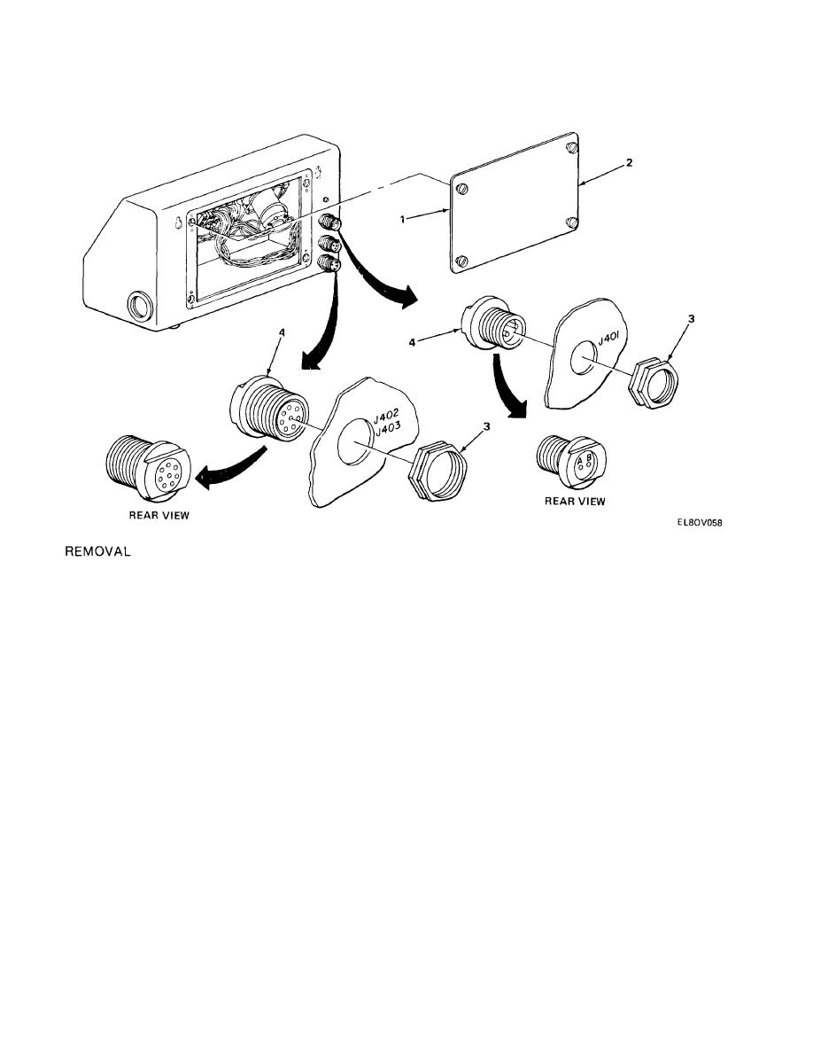
Loosen four turn-lock fasteners (1) and remove rear cover (2).
2.
Remove nut (3) and push connector plug (4) into indicator case.
NOTE
For correct soldering methods, refer to TB SIG 222.
3.
Using soldering iron, unsolder wires one at a time from defective connector plug and resolder
on replacement connector plug.
INSTALLATION
1.
Push connector plug out of hole in indicator case and install nut (3).
2.
Install rear cover (2) and tighten four turn-lock fasteners (1).
5-17

 Previous Page
